
The HC-SR04 module is a specific ultrasonic sensor module commonly used for distance measurement. It comprises an ultrasonic transmitter-receiver pair and control circuitry, all integrated into a small board.
The HC-SR04 operates by sending out a burst of ultrasonic sound waves and then measuring the time it takes to bounce off an object and return to the sensor. Using the known speed of sound in air, the module calculates the distance to the object based on the time it takes for the sound waves to travel to the object and back.
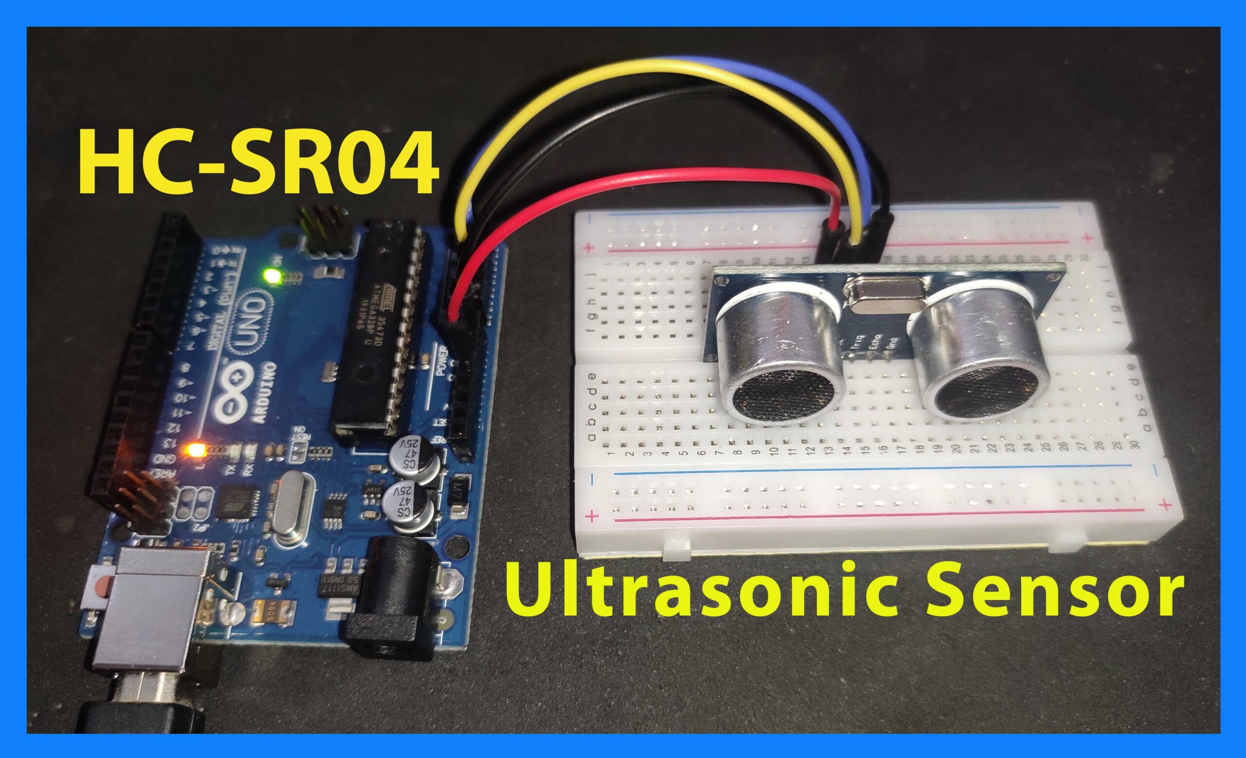
A prominent characteristic of the HC-SR04 module is its straightforwardness and user-friendly nature. Typically demanding only minimal connections to a microcontroller or comparable electronic device for functionality, it is widely favoured among hobbyists, students, and innovators for various projects encompassing robotics, obstacle detection systems, and distance measurement tasks.
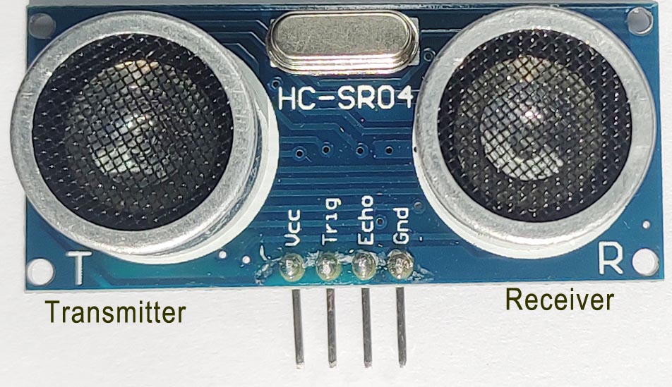
Fig.1
In this module, “T” represents the Transmitter, and “R” denotes the Receiver.

Fig.2
An Ideal Signal timing diagram is shown in Fig 2. The practical timing diagram is captured in an Oscilloscope and is demonstrated in the following sections.
Pin descriptions of HC-SR04:
VCC: VCC is the module’s power pin. +5V DC is applied to this pin.
Trig Pin: This pin is to trigger the module. The duty cycle of the trigger signal should be 10 microseconds or more. The captured trigger pulse is shown in Fig 3.
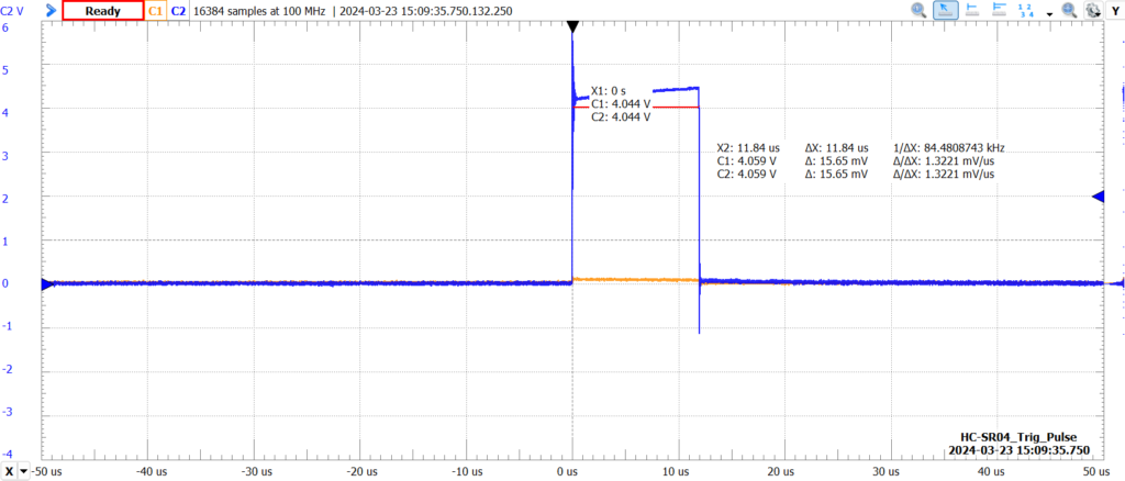
Fig.3
When a High-Level pulse of typically 10 microseconds is given to the trigger pin, the Transmitter of the module transmits a Ultrasonic burst signal of 40KHz consisting of 8 pulses. See the Fig 4.
Ultrasonic 40KHz Burst Signal:
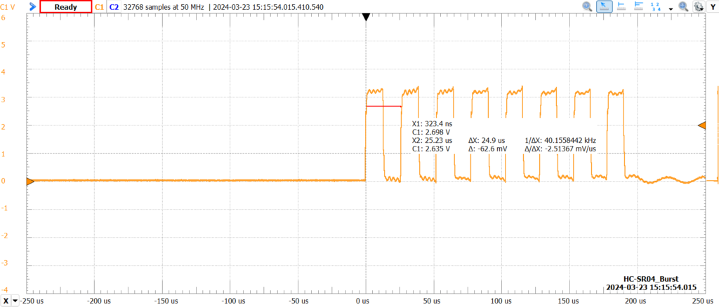
Fig.4
There is approximately a 2ms delay between the trigger pulse’s falling edge and the burst signal’s starting edge in Fig 5.
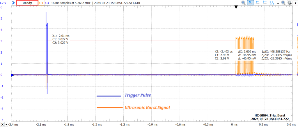
Fig.5
Echo Pin: The output state of the Echo Pin goes high-level just after ultrasonic burst signal transmission is completed. When the reflected ultrasonic signal from any obstacle is received at the receiver, the Echo pin goes low. This way, a pulse appears on the Echo Pin which duration is equal to the total travel time of the ultrasonic burst signal Fig 6 and Fig 7.
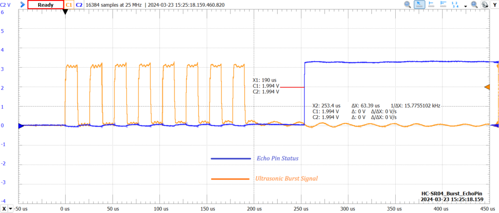
Fig.6
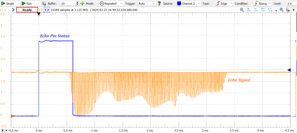
Fig.7
Ground: This is the common ground of the module and is connected to the Arduino Board’s common ground.
Measurement of distance:
When a trigger pulse is sent to the module, an ultrasonic burst signal is transmitted from the transmitter, the echo pin is set to HIGH, and a timer counter starts. Then, wait for the echo signal to be received on the module’s receiver. When the echo is received, the Echo Pin sets to LOW status, and the timer stops. The time between sending the Ultrasonic burst signal and receiving the echo signal is equal to the duty cycle of the pulse received from the Echo Pin.
Use the formula below to calculate the distance to the obstacle based on the time measured:
The speed of sound in air at room temperature is approximately 346 meters per second (m/s).
Since the ultrasonic pulse travels to the object and back, we divide the total time by 2 to get the one-way distance.
\(Time = \frac{Total \;Travel\; Time \;of\; Ultrasonic\; burst\; signal}{2} \; \)
\(Distance = {Speed\; of \;Sound}\times\ {Time}\)
Connection with Arduino:
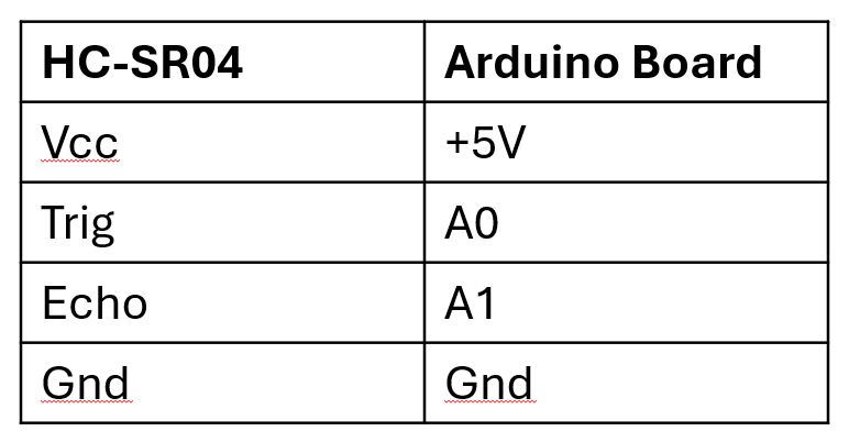
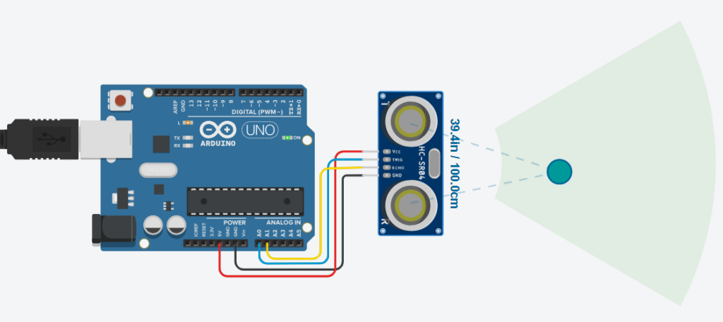
Fig.8
Arduino Code:
Assign the Trigger and Echo pin to the Arduino board. Also, the pins can be assigned to any Arduino IO pins. In this tutorial, A0 and A1 are used.
const char trigPin = A0;
const char echoPin = A1;
Initial setups
void setup() {
  pinMode(trigPin, OUTPUT); // configure trigger pin as OUTPUT pin
  pinMode(echoPin, INPUT); // configure echo pin as INPUT pin
  digitalWrite(trigPin, LOW); // initially set trigger pin LOW
  Serial.begin(9600); // serial baud rate
}
This code sends the trigger pulse of 10 microseconds to transmit the Ultrasonic burst signal.
digitalWrite(trigPin, HIGH);
delayMicroseconds(10);
digitalWrite(trigPin, LOW);
pulseIn(arg, arg) is the inbuilt Arduino function that counts the duration of any pulse. It can be configured on either edge of the pulse signal.
In this code, when the echo pulse goes HIGH, it starts the timer, and when the echo pulse goes LOW, it stops the counting and returns the pulse duration in microSeconds.
duration = pulseIn(echoPin, HIGH); //capture the duration (in uS) of the pulse received from echo pin
Complete Arduino Code:
const char trigPin = A0;
const char echoPin = A1;

float duration, distance; //global variables

void setup() {
  pinMode(trigPin, OUTPUT); // configure trigger pin as OUTPUT pin
  pinMode(echoPin, INPUT); // configure echo pin as INPUT pin
  digitalWrite(trigPin, LOW); // initially set trigger pin LOW
  Serial.begin(9600); // serial baud rate
}

void loop() {
  digitalWrite(trigPin, HIGH);
  delayMicroseconds(10);
  digitalWrite(trigPin, LOW);
  duration = pulseIn(echoPin, HIGH); //capture the duration(in uS) of the pulse received from echo pin
  duration /=1000;  // convert the duration in millSeconds
  duration /=1000;  // again convert the duration in Seconds
  distance = (duration*346*100)/2;  //  Calculation of distance of an object in Centimeter
  Serial.print("Distance: ");
  Serial.print(distance);
  Serial.println(" cm");
  delay(200);

}