
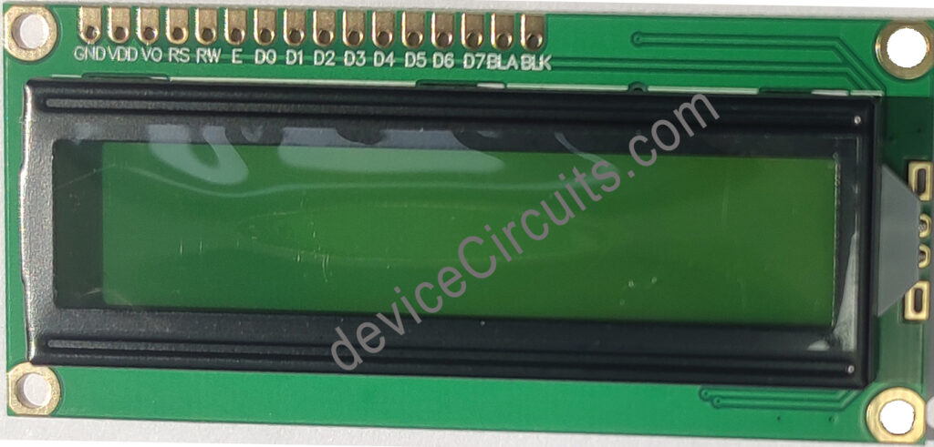
An LCD (Liquid Crystal Display) module with a 16×2 configuration is commonly employed in electronics projects, especially those involving microcontroller-based systems like the Arduino. The “16×2” specification denotes its dimensions: it features 16 characters per line across 2 lines, resulting in a total display width of 32 characters. Each character typically consists of a 5×8 pixel matrix, although variations in character size may occur based on the chosen font.
These displays often come equipped with a controller, such as the HD44780, which simplifies interaction with microcontrollers. The controller handles tasks like character generation and display management. These LCD modules typically offer either a parallel or serial interface for communication with the microcontroller. They can display a range of content, including alphanumeric characters, symbols, and custom-defined characters.
Due to their simplicity, affordability, and ease of use, 16×2 LCD displays find widespread application in digital clocks, temperature displays, message boards, and menu interfaces.
4-bit mode Interface
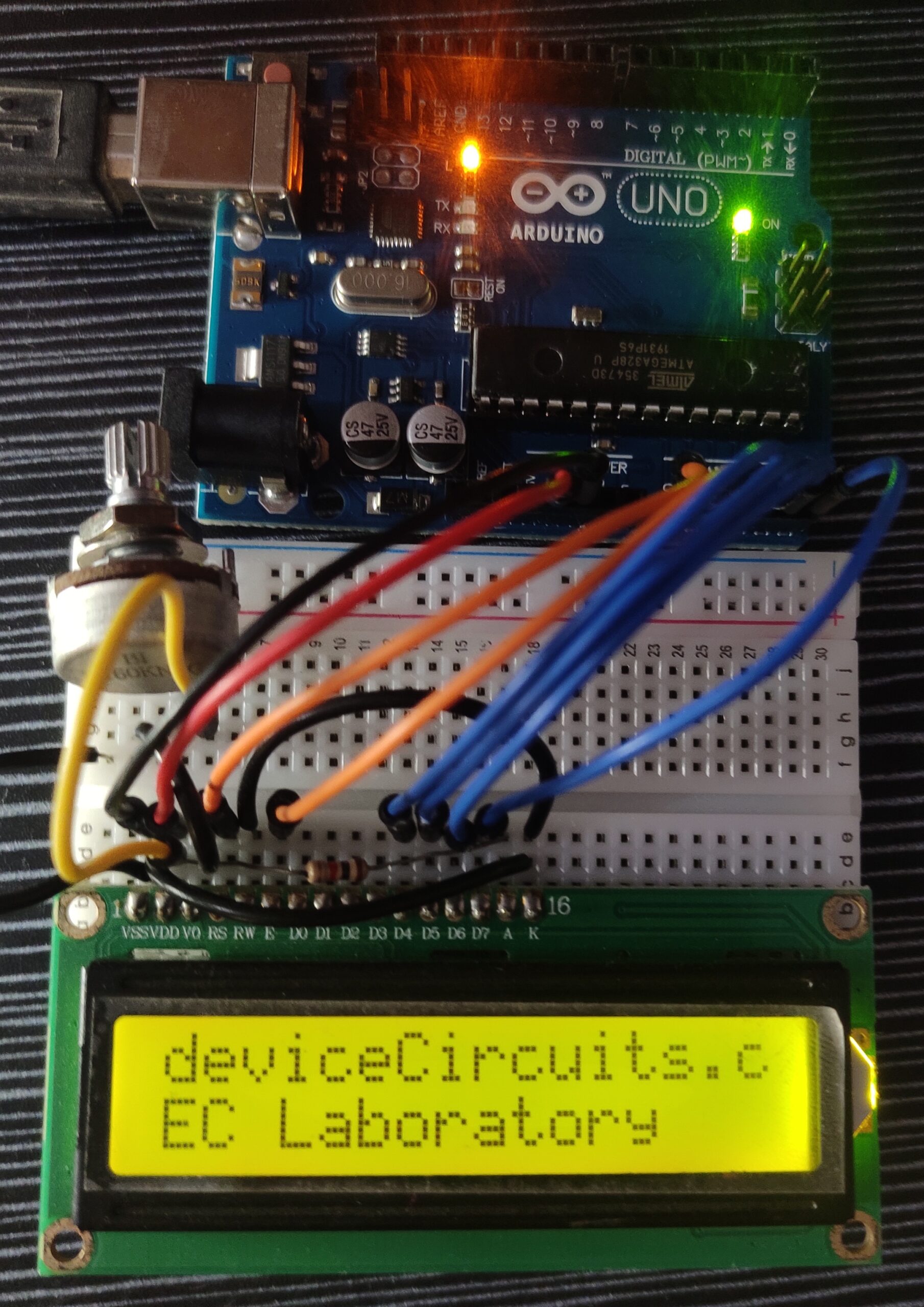
A 4-bit data mode connection diagram is given below. In this configuration, Arduino analog pins are used. But any analog or digital pin can be assigned.

| 16×2 LCD pin | Arduino Uno / Nano pin |
| Vss | GND |
| Vdd | 5V |
| Vo | Intensity control voltage. Connect a 10k Potentiometer to control the intensity. |
| RS | A0 |
| RW | GND (Active Low) |
| E | A1 |
| D0 | NC |
| D1 | NC |
| D2 | NC |
| D3 | NC |
| D4 | A2 |
| D5 | A3 |
| D6 | A4 |
| D7 | A5 |
| A | VDD with a series resistor (330R – 1K) |
| K | GND |
Arduino Code
#include <LiquidCrystal.h>

// Initialize the LCD object
LiquidCrystal lcd(A0, A1, A2, A3, A4, A5); // (RS, E, D4, D5, D6, D7)

void setup() {
  // Initialize the LCD with 16 columns and 2 rows
  lcd.begin(16, 2);

}

void loop() {
  lcd.setCursor(0, 0);//(col, row)
  lcd.print("deviceCircuits.com");
  lcd.setCursor(0, 1);//(col, row)
  lcd.print("EC Laboratory");
  delay(500);
}