
The HC-05 Bluetooth module is a popular wireless communication device that can add two-way (full-duplex) functionality in electronics projects. It enables wireless communication between devices using Bluetooth technology. The module is popular among hobbyists, makers, and electronics enthusiasts due to its ease of use, affordability, and versatility. It typically operates as a serial communication device, allowing microcontrollers like Arduino to communicate wirelessly with Bluetooth-enabled devices such as smartphones, tablets, or other microcontrollers. The HC-05 module can be configured as a master or slave device, making it suitable for a variety of applications, including wireless data transmission, remote control, and sensor networks.
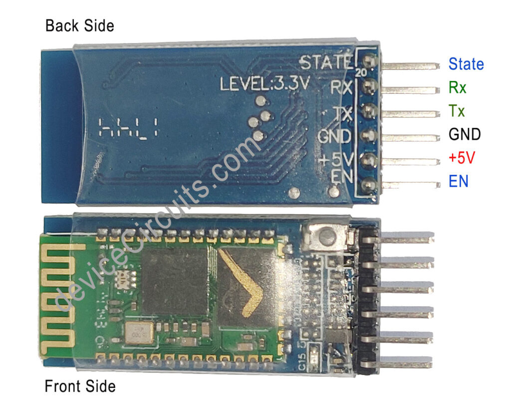
Pin Descriptions:

EN (Enable): This pin switches between Data Mode (when set low) and AT command mode (when set high). I left this floating for command mode.
Vcc: Powers the module. Connect it to a +5V supply voltage. There is an internal 3.3v LDO, which converts 5v to 3.3v to supply the required voltage to the module.
Ground : This pin is system ground, and it should be connected to the ground pin of the Arduino board.
TX (Transmitter): This pin transmits the data serially from the module to the Arduino board. Anything received via Bluetooth will be output through this pin.
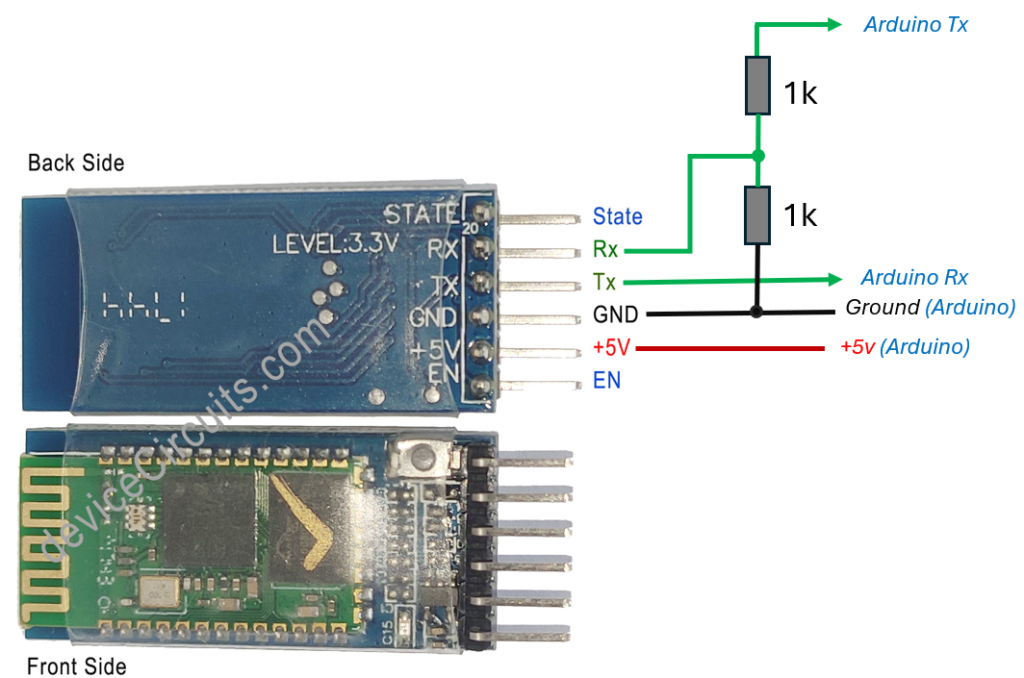
RX (Receiver): This pin receives data serially. Any serial data input to this pin will be transmitted via Bluetooth. The logic level of this pin is typically 3.3v, so there is a need for a resistor voltage divider for the proper operation of the module. Even though this module works at a 5v logic level, this is not recommended as per the datasheet.
State: This pin provides feedback on whether Bluetooth is connected and functioning correctly. If it is high, then the module is connected, and if it is set to low, it is not connected.
Onboard LED: There is an onboard LED which Indicates the module’s status:
It blinks once every 2 seconds which indicates Module is in Command Mode.
Repeated blinking indicates awaiting connection in Data Mode.
Blink twice every 1 second indicates successful connection in Data Mode.
Onboard Button: Used to control the Enable pin for toggling between Data and Command Mode.
Default Settings:
Device Name: “HC-05” This name is appear when it is scanned by other device.
Password: 1234
Communication Mode: Slave
Default Baud Rate (Data Mode): 9600
Default Baud Rate (Command Mode): 38400, Data bits:8, Stop bit:1, Parity: No parity
Technical Specifications:
Bluetooth Version: Bluetooth 2.0+EDR (Enhanced Data Rate)
Operating Frequency: 2.4 GHz ISM band
Antenna: Integrated PCB trace antenna
Communication Interface: Serial communication (USART) and TTL-compatible devices
Operating Voltage: +5V
Logic Level: 3.3v
Communication Range: Typically up to 10 meters (Class 2)
Bluetooth Profiles: Supports Bluetooth Serial Port Profile (SPP)
Protocol: IEEE 802.15.1 standard
Mode: Master, Slave, or Master/Slave mode
Supported baud rates: 9600, 19200, 38400, 57600, 115200, 230400, 460800
It is not suitable for multimedia transfer (photos, songs).
Arduino Code
#include <SoftwareSerial.h>

SoftwareSerial HC05(2, 3); // RX = 2, TX = 3 // user can assign any pin as per availability
char receivedData;  // Variable to store data in character format

void setup()
{
  Serial.begin(9600);
  Serial.println("HC05 serial started at 9600");
  HC05.begin(9600); // set HM10 serial at 9600 baud rate
  pinMode(13, OUTPUT); // onboard LED
  digitalWrite(13, LOW); // initially switch OFF LED
}

void loop()
{
  // Transmitter  ////
  if (Serial.available()) {     // Check user data if available on serial port for transmission
    delay(10);
    HC05.write(Serial.read()); // Read the user data on serial port buffer, and send it to BT module for transmission
  }

  /// Receiver  ////

  HC05.listen();  // listen the HM10 port
  while (HC05.available() > 0) {   // if HM10 sends something then read
    receivedData = HC05.read(); //read single char or 1-Byte
  }

  if (receivedData == '1') {
    Serial.print("Received Command: ");
    Serial.println("led off");
    Serial.println("LED De-activated");
    digitalWrite(13, LOW); // switched OFF LED
    HC05.write("LED De-activated Successfully");
    HC05.write('\n');
    delay(500);
  }

  if (receivedData == '2') {
    Serial.print("Received Command: ");
    Serial.println("led on");
    Serial.println("LED Activated");
    digitalWrite(13, HIGH); // switched ON LED
    HC05.write("LED Activated Successfully");
    HC05.write('\n');
    delay(500);

  }
}
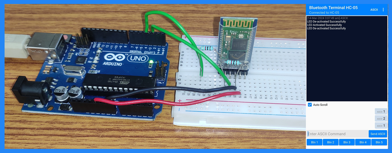
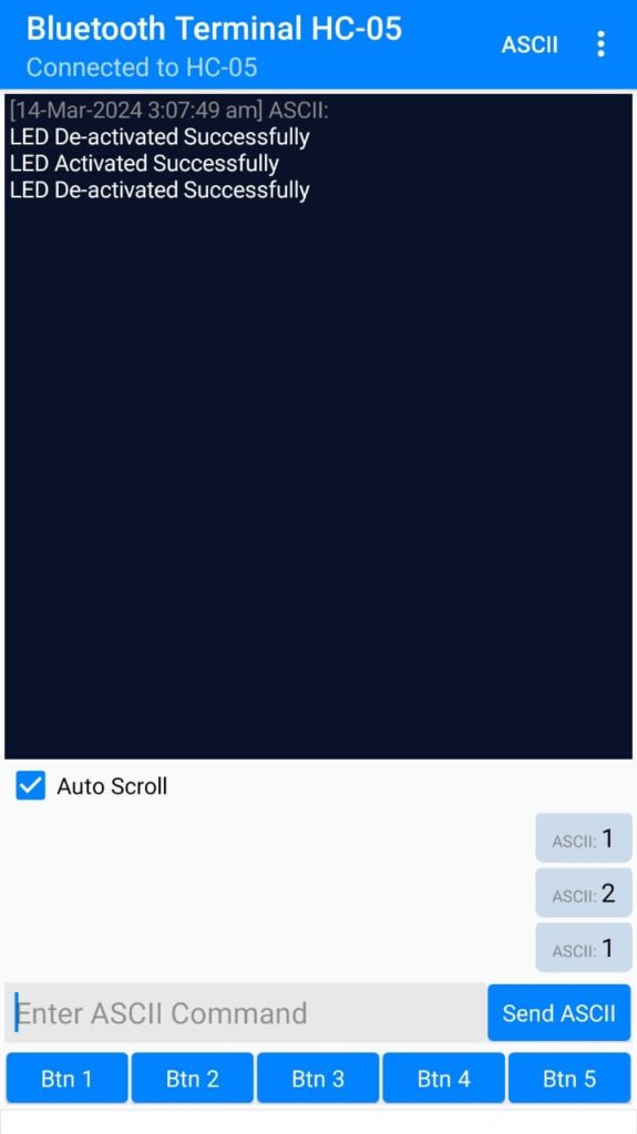
Android App
Download Android App “Bluetooth Terminal HC-05” from Google Play Store.
Troubleshoot
Ensure that you have correctly connected the Rx and Tx connections. The module’s Rx pin should be connected to the Arduino’s Tx pin, and vice versa. In this tutorial, Arduino’s digital pin 2 serves as the Rx pin, while pin 3 functions as the Tx pin.